Pics and Status Of My Turbo-NA-Bridgeport Engine Build
 08-04-04, 06:17 PM
#1
Engine, Not Motor
Thread Starter
iTrader: (1)
Join Date: Feb 2001
Location: London, Ontario, Canada
Posts: 29,789
Likes: 0
Received 108 Likes
on
91 Posts
OK guys and gals, here's another chapter of my Project Tina build. In this episode, we put together the half-bridge turbo-NA engine. In case you missed our last action packed adventure, you can find the thread here.
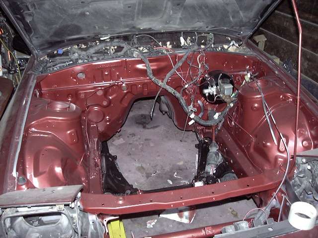
When we last left our intrepid hero (OK, I'm stopping with the comic book narration now), the engine bay had just been given a quick coat of Cherry metallic, and it was time to actually assemble the engine that would live there.
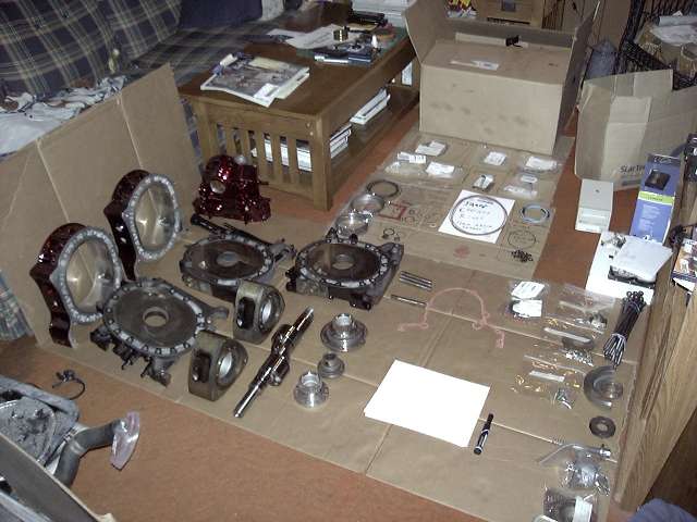
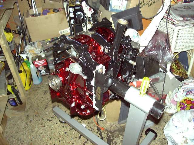
Laid out here is every hard part, gasket and seal required to assemble one 13B short block. Everything has been given it's final cleaning, and it's all organized with clearly written labels to avoid confusion during the build.
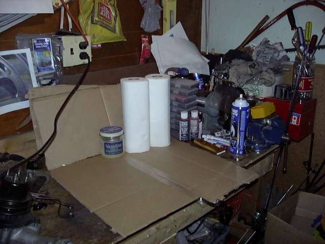
Here's the rotor assembly area. A clean space is needed to install all the necessary seals on the rotor beforehand. It's a time consuming procedure, and you don't want to stop a build everytime you need a rotor. You can also just barely see a note written in marker that says "Apex corner seal towards intermediate". This is to remind me that the corner apex piece must face the center of the engine to prevent them from falling through the eyebrow port.
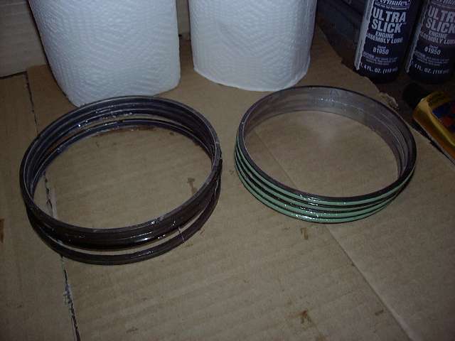
The oil o-rings were first assembled. The rings are coated with Vascelene and then rolled into the metal carrier. This must be carefully done to avoid twisting the rubber ring.
Sorry to skip so many steps, but I just went ahead and assembled the rotors without bothering to take too many pictures. Vascelene is used to hold everything in place, and it's a pain to clean your hands every step to take the picture. Essentially, the oil springs are put in place, then the rings themselves. I then install the corner seals, then the side seals, then slide in the apex seals (leaving out the springs). Everything is then covered in Vascelene to keep it in place. I also prelube underneath the oil rings with assembly lube.
When we last left our intrepid hero (OK, I'm stopping with the comic book narration now), the engine bay had just been given a quick coat of Cherry metallic, and it was time to actually assemble the engine that would live there.
Laid out here is every hard part, gasket and seal required to assemble one 13B short block. Everything has been given it's final cleaning, and it's all organized with clearly written labels to avoid confusion during the build.
Here's the rotor assembly area. A clean space is needed to install all the necessary seals on the rotor beforehand. It's a time consuming procedure, and you don't want to stop a build everytime you need a rotor. You can also just barely see a note written in marker that says "Apex corner seal towards intermediate". This is to remind me that the corner apex piece must face the center of the engine to prevent them from falling through the eyebrow port.
The oil o-rings were first assembled. The rings are coated with Vascelene and then rolled into the metal carrier. This must be carefully done to avoid twisting the rubber ring.
Sorry to skip so many steps, but I just went ahead and assembled the rotors without bothering to take too many pictures. Vascelene is used to hold everything in place, and it's a pain to clean your hands every step to take the picture. Essentially, the oil springs are put in place, then the rings themselves. I then install the corner seals, then the side seals, then slide in the apex seals (leaving out the springs). Everything is then covered in Vascelene to keep it in place. I also prelube underneath the oil rings with assembly lube.
 08-04-04, 06:18 PM
#2
Engine, Not Motor
Thread Starter
iTrader: (1)
Join Date: Feb 2001
Location: London, Ontario, Canada
Posts: 29,789
Likes: 0
Received 108 Likes
on
91 Posts
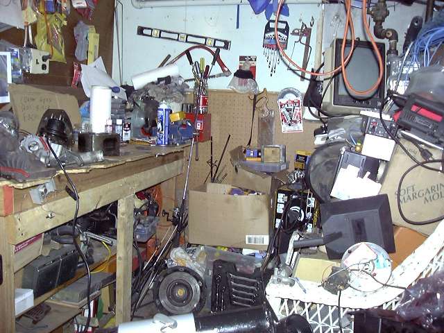
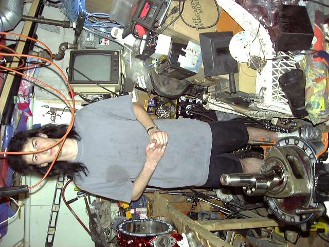
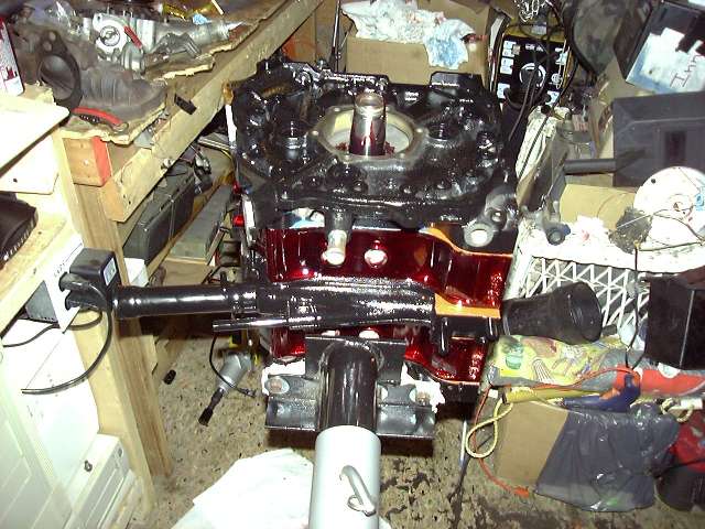
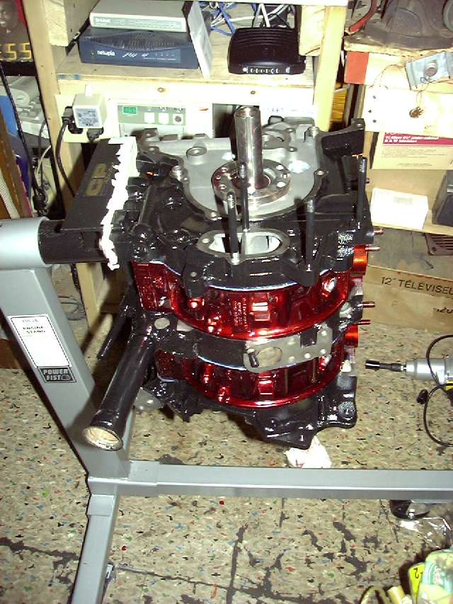
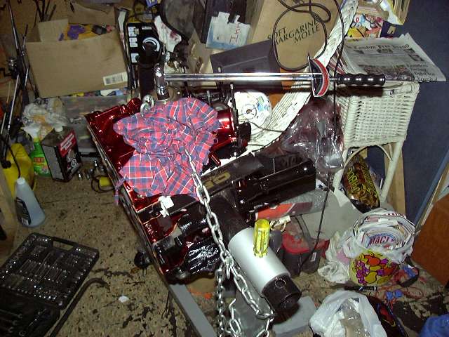
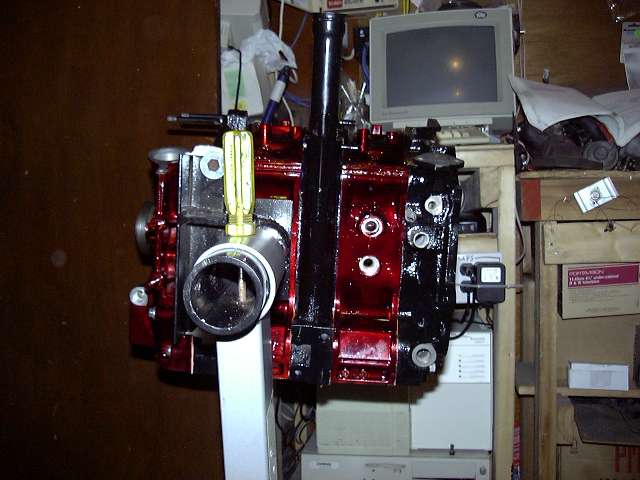
Here's a general picture of the work area. Yes, it's quite messy. I have 24.5 years of valuable junk stored in that room.
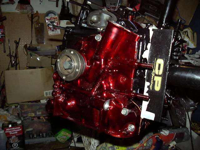
The front iron mounted on the engine stand. I would certainly recommend an engine stand to anyone doing this. Yes, it could be done on a table or bench, but it would be a major pain in the butt. A stand allows you to easily rotate the engine, and move it around as necessary. I got my engine stand adapter from CP Racing. They build them in house out of thick steel, and much cheaper then Mazdatrix.
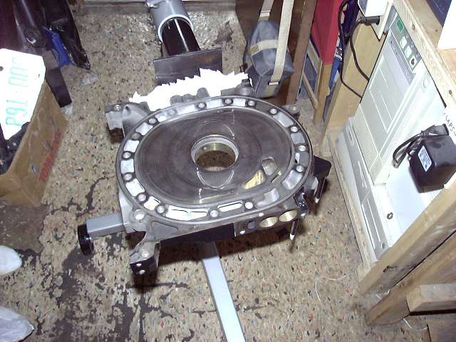
First, the front stationary gear gets installed snugly with 1 bolt. It's an interference fit, so the gear must be pushed in exactly perpendicular to the iron. Assembly lube around the outer circumfrence helps greatly.
Here, the coolant o-rings are installed. They are first covered with Hylomar (a non-hardening, non-drying gasket dressing/sealant) and then pressed into place. The black o-ring goes in the outer groove (make sure the white mark is NOT facing top or bottom) and the red/green o-ring goes in the inner groove (place the joint in the ring above the intake port). The hylomar holds everything place and prevents horrible o-ring pinching (a sure way to make a water pumper).
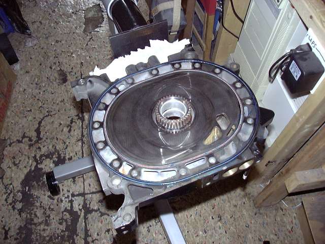
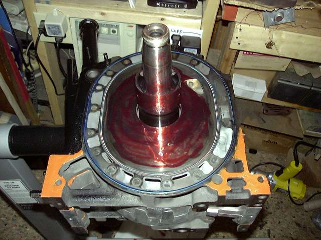
The front iron is now pre-lubed with engine assembly lube, and is ready to have the eccentric and front rotor installed.
The front iron mounted on the engine stand. I would certainly recommend an engine stand to anyone doing this. Yes, it could be done on a table or bench, but it would be a major pain in the butt. A stand allows you to easily rotate the engine, and move it around as necessary. I got my engine stand adapter from CP Racing. They build them in house out of thick steel, and much cheaper then Mazdatrix.
First, the front stationary gear gets installed snugly with 1 bolt. It's an interference fit, so the gear must be pushed in exactly perpendicular to the iron. Assembly lube around the outer circumfrence helps greatly.
Here, the coolant o-rings are installed. They are first covered with Hylomar (a non-hardening, non-drying gasket dressing/sealant) and then pressed into place. The black o-ring goes in the outer groove (make sure the white mark is NOT facing top or bottom) and the red/green o-ring goes in the inner groove (place the joint in the ring above the intake port). The hylomar holds everything place and prevents horrible o-ring pinching (a sure way to make a water pumper).
The front iron is now pre-lubed with engine assembly lube, and is ready to have the eccentric and front rotor installed.
08-04-04, 06:19 PM
#3
Engine, Not Motor
Thread Starter
iTrader: (1)
Join Date: Feb 2001
Location: London, Ontario, Canada
Posts: 29,789
Likes: 0
Received 108 Likes
on
91 Posts
To install the front rotor, it is placed so that an apex points down and all apexs are within the proper running area. The gear is then meshed with the front stationary gear. Really, it only fits one way.
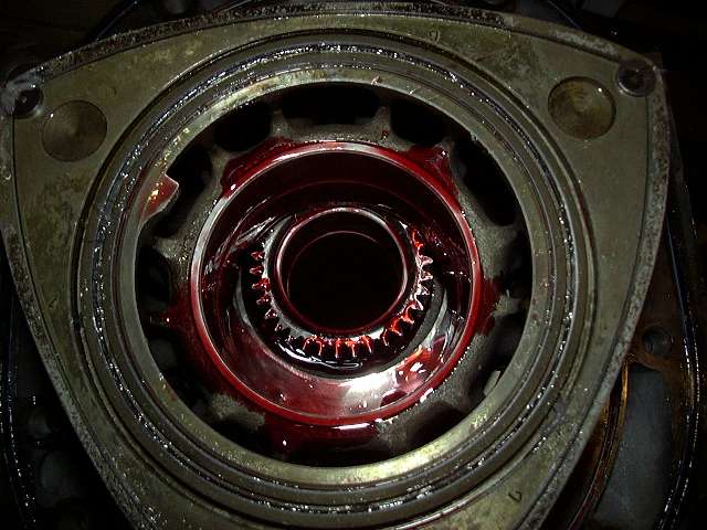
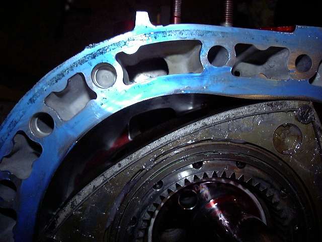
An extreme closeup of the front rotor bearing and stationary gear after things have been thoroughly covered in assembly lube. You can never lube too much, especially if the engine will be sitting a while before starting (as this one will).
The eccentric is then carefully lowered into place after all bearings are lubed. You don't want to make the shaft slippery because it's too easy to drop.
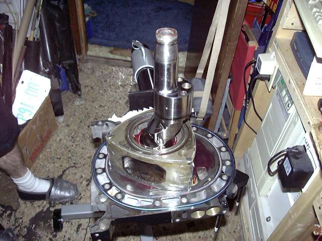
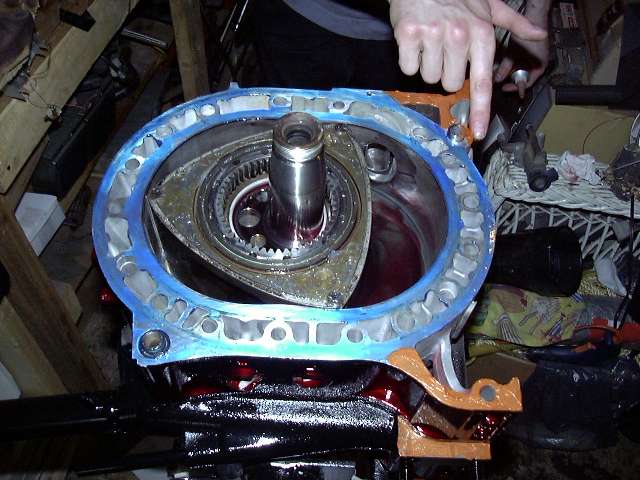
After the extra hylomar was cleaned from the "legs" of the iron....
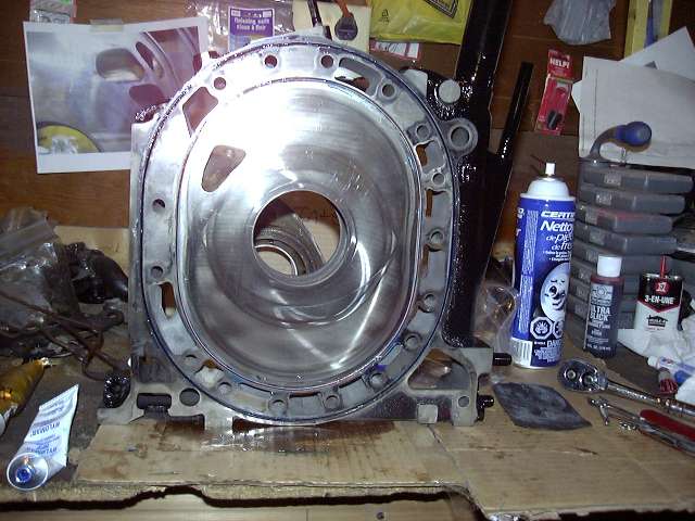
...it was time to place the front housing. Here you see the housing with it's mating surfaces coated in hylomar. BTW, hylomar makes a huge mess, so keep plenty of paper towels ready.
An extreme closeup of the front rotor bearing and stationary gear after things have been thoroughly covered in assembly lube. You can never lube too much, especially if the engine will be sitting a while before starting (as this one will).
The eccentric is then carefully lowered into place after all bearings are lubed. You don't want to make the shaft slippery because it's too easy to drop.
After the extra hylomar was cleaned from the "legs" of the iron....
...it was time to place the front housing. Here you see the housing with it's mating surfaces coated in hylomar. BTW, hylomar makes a huge mess, so keep plenty of paper towels ready.
08-04-04, 06:19 PM
#4
Engine, Not Motor
Thread Starter
iTrader: (1)
Join Date: Feb 2001
Location: London, Ontario, Canada
Posts: 29,789
Likes: 0
Received 108 Likes
on
91 Posts
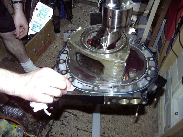
Sealant is needed on the legs of the iron. The Renesis seems to have grooves in this place to hold the sealant more effectivly. Us 13B people just have to hope we don't get oil seepage.
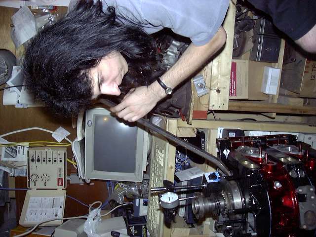
Your's truly...sideways.
Installing the front rotor housing over the dowels. This is the process of building a "Dagwood sandwich". Note slight lube on the dowels. Makes it easier to slide the housing down.
The front housing is installed. Now, the apex seal springs need to be inserted. This is done by removing the corner seals, then pushing the apex seal springs in. The small one goes in first and gets pushed as far as it will go, with the aid of a pick. After that, the large spring is pushed in until it "clicks". This click is made by the smaller spring self adjusting, and the large spring going over the bump on the apex corner. Contrary to what most people think, the mouth of the apex seal spring faces TOWARD the seal, not toward the rotor. Now the corner seal is reinstalled.
A close up of the rotor showing the apex seal, corner seal and assembly lube.
08-04-04, 06:19 PM
#5
Engine, Not Motor
Thread Starter
iTrader: (1)
Join Date: Feb 2001
Location: London, Ontario, Canada
Posts: 29,789
Likes: 0
Received 108 Likes
on
91 Posts
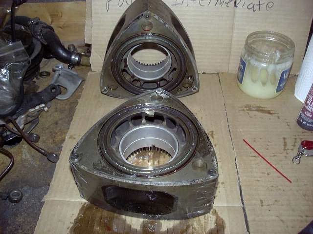
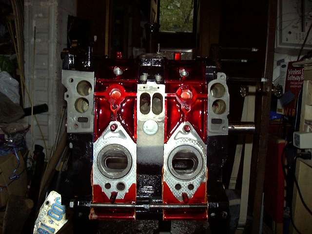
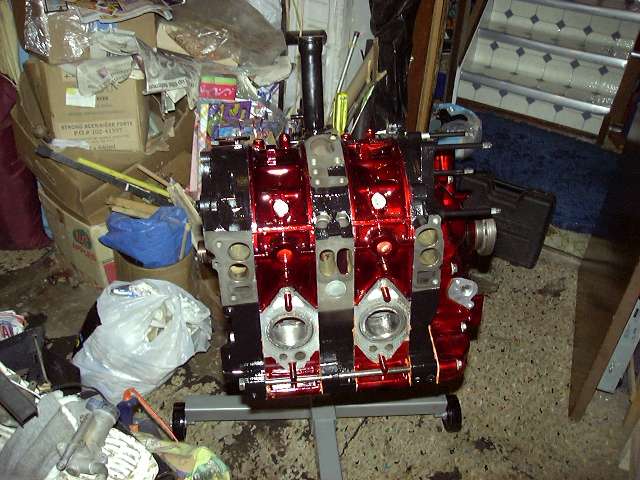
Another closeup showing the ports and how the eyebrow looks against the housing. If I had been thinking, we would have rotated the rotor to illustrate how early a bridgeport opens compared to stock.
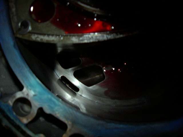
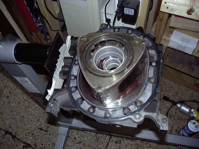
The intermediate is clean and ready to go. The shadows and flash make the primary ports look pretty crappy, but they're decent. I could have actually gone larger.
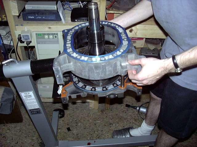
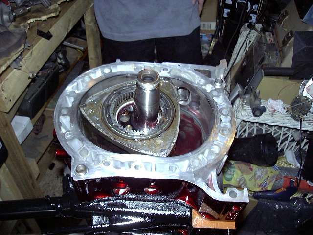
Next the intermediate was lowered in place. This is a two person job, as one person must push the eccentric up about an inch while the other rocks the housing over the lobe and onto the dowels. Thanks to Snrub for being there and providing the extra set of hands when necessary, as well as taking most of the pictures. It also helps to put the o-rings on both sides of the intermediate first. Don't forget the dowel o-rings!
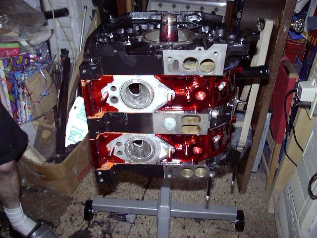
Second shot of the intermediate, this time from the port side.
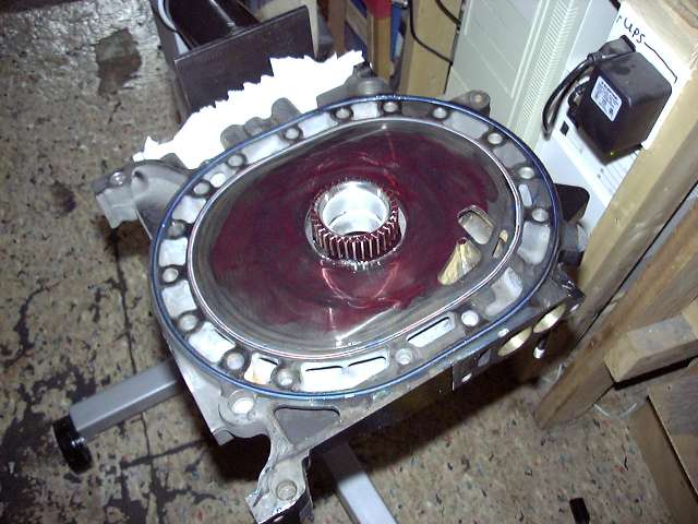
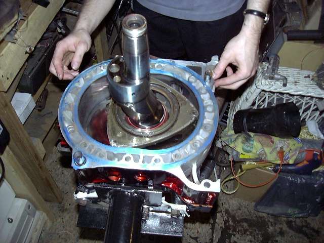
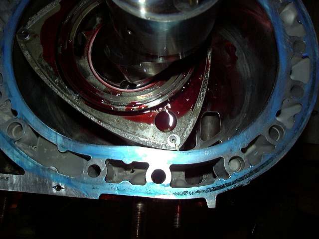
It's time to install the rear rotor, so the intermediate and eccentric was lubed up in preparation. It's kind of creepy how much the stuff looks like blood...(finally, I could have used the vampyre smiley, but it's no longer here...)
The intermediate is clean and ready to go. The shadows and flash make the primary ports look pretty crappy, but they're decent. I could have actually gone larger.
Next the intermediate was lowered in place. This is a two person job, as one person must push the eccentric up about an inch while the other rocks the housing over the lobe and onto the dowels. Thanks to Snrub for being there and providing the extra set of hands when necessary, as well as taking most of the pictures. It also helps to put the o-rings on both sides of the intermediate first. Don't forget the dowel o-rings!
Second shot of the intermediate, this time from the port side.
It's time to install the rear rotor, so the intermediate and eccentric was lubed up in preparation. It's kind of creepy how much the stuff looks like blood...(finally, I could have used the vampyre smiley, but it's no longer here...)
08-04-04, 06:20 PM
#6
Engine, Not Motor
Thread Starter
iTrader: (1)
Join Date: Feb 2001
Location: London, Ontario, Canada
Posts: 29,789
Likes: 0
Received 108 Likes
on
91 Posts
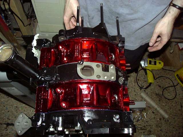
The rear rotor is placed. This picture also shows an absolute necessity in an engine build: Dr. Pepper.
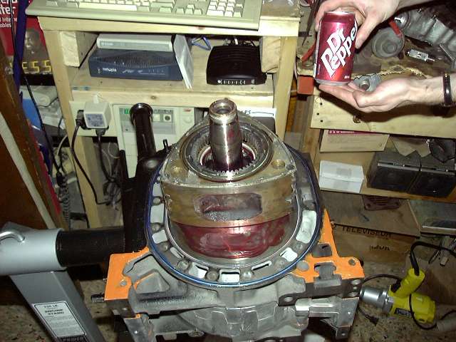
Initially, I forgot to super glue the apex seal corners in place before this housing was installed. This prevented the installation of the springs (the big one would catch on the gap created by the corner piece). So we needed to pull the housing, glue the seals, and then put the housing back. The springs then slid easily into place. This is not normally a problem as in a non-bridged engine the corner piece would face the rear of the engine.
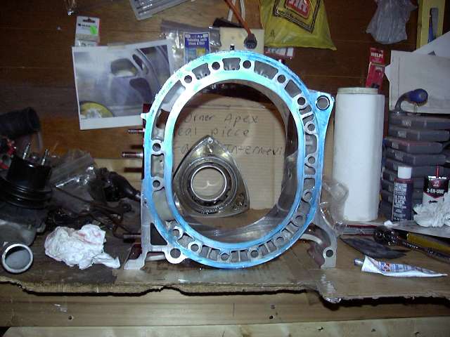
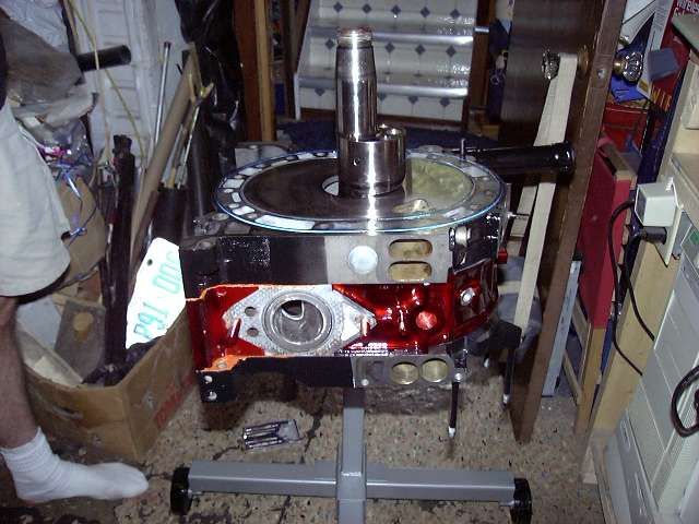
Sealants being spread on the rear housing. You can see the blue hylomar on the o-ring surface, and the copper silicone on the legs. Messy job.
Just a closeup of the rotor's eye view of the housing, ports, etc.
And the rear plate was lowered into place. Don't forget the o-rings on the dowels!
Initially, I forgot to super glue the apex seal corners in place before this housing was installed. This prevented the installation of the springs (the big one would catch on the gap created by the corner piece). So we needed to pull the housing, glue the seals, and then put the housing back. The springs then slid easily into place. This is not normally a problem as in a non-bridged engine the corner piece would face the rear of the engine.
Sealants being spread on the rear housing. You can see the blue hylomar on the o-ring surface, and the copper silicone on the legs. Messy job.
Just a closeup of the rotor's eye view of the housing, ports, etc.
And the rear plate was lowered into place. Don't forget the o-rings on the dowels!
08-04-04, 06:20 PM
#7
Engine, Not Motor
Thread Starter
iTrader: (1)
Join Date: Feb 2001
Location: London, Ontario, Canada
Posts: 29,789
Likes: 0
Received 108 Likes
on
91 Posts
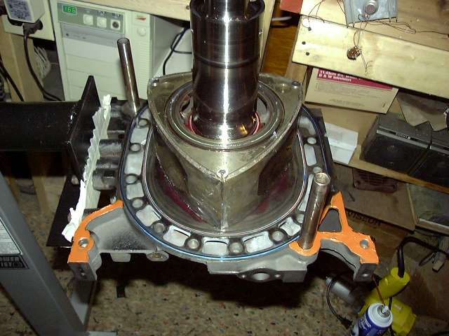
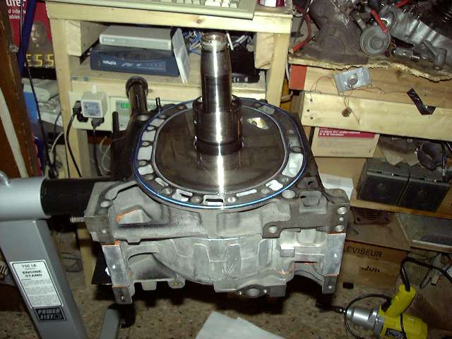
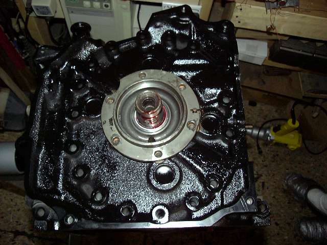
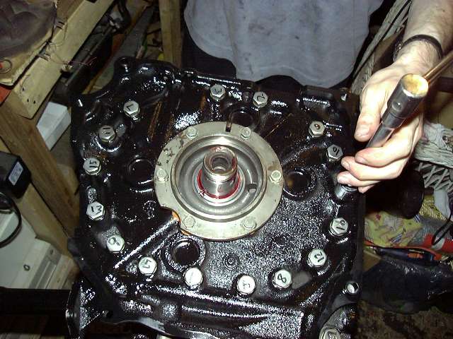
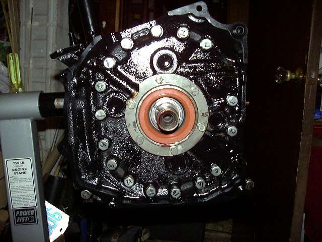
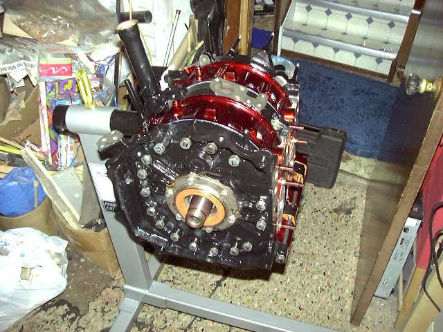
Another view of the rear plate.
I then install the rear stationary gear. Of course, the bearing and shaft are lubed. There is also an o-ring that fits around the outside of the gear, and a VERY thin layer of sealant is put on the flange.
Time for the tension bolts. It's a satisfying feeling to ram each one of those suckers into place.
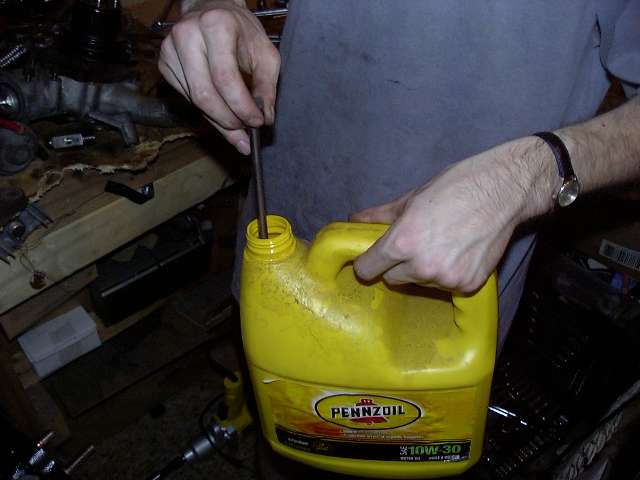
A small amount of oil on the threads assures even torque.
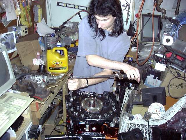
Now the pain: torquing them. It's done in three steps, to either 34 or 28 LB (I forget now). And it must be done in the order as shown by the numbers on the heads.
I then install the rear stationary gear. Of course, the bearing and shaft are lubed. There is also an o-ring that fits around the outside of the gear, and a VERY thin layer of sealant is put on the flange.
Time for the tension bolts. It's a satisfying feeling to ram each one of those suckers into place.
A small amount of oil on the threads assures even torque.
Now the pain: torquing them. It's done in three steps, to either 34 or 28 LB (I forget now). And it must be done in the order as shown by the numbers on the heads.
Trending Topics
08-04-04, 06:21 PM
#8
Engine, Not Motor
Thread Starter
iTrader: (1)
Join Date: Feb 2001
Location: London, Ontario, Canada
Posts: 29,789
Likes: 0
Received 108 Likes
on
91 Posts
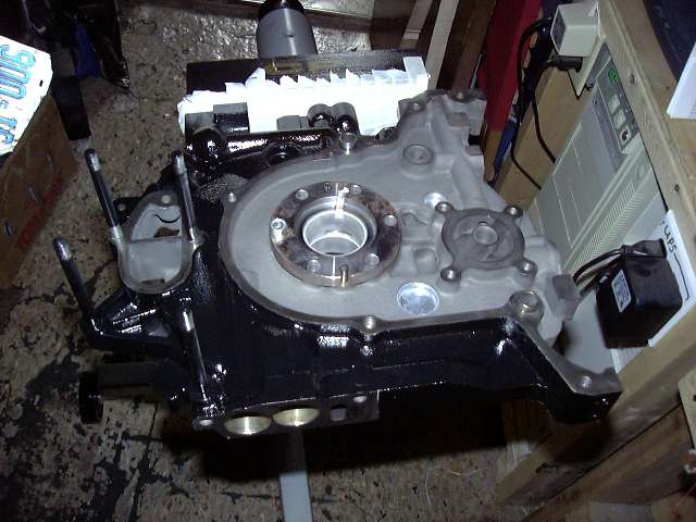
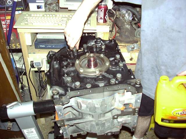
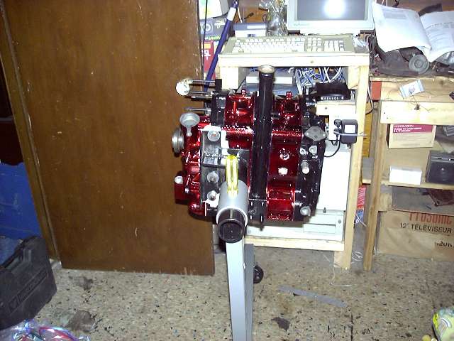
And here we have some views of the finished short block. The excess sealant is easily peeled off once it has completely cured. The next step is to set the eccentric end play, install the thrust plate, install the oil pump, front cover and hub.
Checking the eccentric shaft end play is VERY important. This measurement is how much the eccentric shaft is allowed to move front to back. This happens, for example, everytime the clutch is pressed or released. The movement is set by 2 bearings and a spacer. To set the end play, the front assembly is put together without the front cover. A dial indicator is then used to measure the play of the front hub while the counterweight is pried up firmly with a bar. I believe that the factory spec is 0015" to .0028". I ended up with about 0.040" on the first attempt, which was the result of worn bearings. So I ended up just buying new bearings and a V spacer (there are about 8 lettered spacers with different thicknesses with which you use to set your play). After installing and rechecking, I came out with about 0.0020", which was right where I wanted it to be. For the record, most factory engines have a V spacer, so if you need to replace bearings, you might as well order the V spacer as well.
 08-04-04, 06:21 PM
#9
Engine, Not Motor
Thread Starter
iTrader: (1)
Join Date: Feb 2001
Location: London, Ontario, Canada
Posts: 29,789
Likes: 0
Received 108 Likes
on
91 Posts
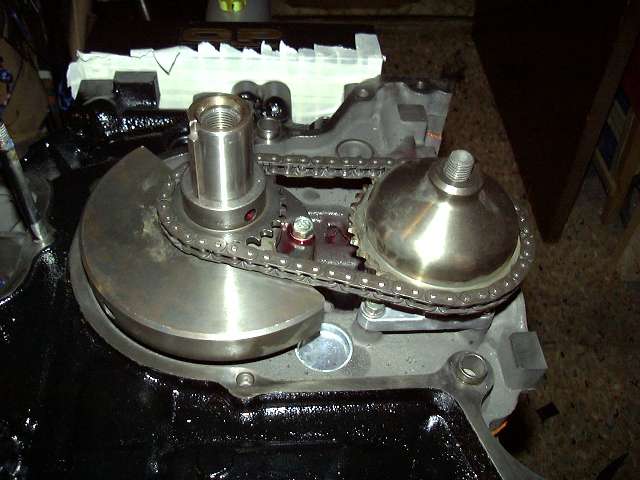
Now that the end play was set, it's time to actually assemble the front half. Here you see the front counterweight and oil pump. Of course, the proper spacer, bearings and thrust plate were installed under the counterweight, and the stationary bolts torqued to about 17 ft-LBS. Both the pump and bearings were thoroughly pre-lubed. The pump bolts get torqued to about 7 ft-lbs, and red Loctite is very important to keep the bolts from backing out.

After that, the oil pump chain and sprockets were installed. This is a little challenging because everything has to line up. Someone needs to make an oil pump gearset, instead of a chain that will stretch.
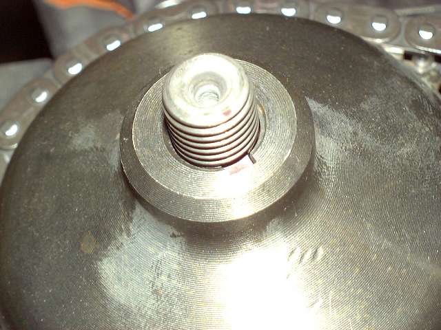
A closeup of the pump sprocket key. This is VERY important. Many engines have been lost because this key has slipped out during assembly. The result is that the sprocket begins to rotate on the shaft, the engine looses oil pressure, and then seizes. It's best to super glue it in place, but mine was already thoroughly stuck, so I didn't need to.
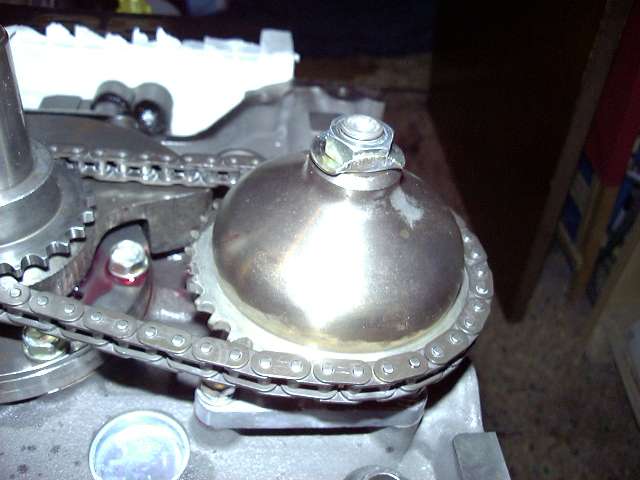
The pump shaft bolt gets torqued, and then the lock washer is bent up around the nut. That nut isn't going anywhere.
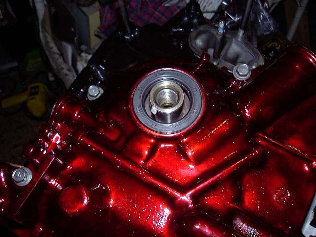
The front cover is installed. This is another "gotcha". There is an o-ring that seals the front cover oil passage to the front iron. Mazda has changed the design of the ENGINE SIDE of the o-ring groove several times (one from S4 to S5). I'm not going to explain it here, so if you are curious you need to visit the Mazdatrix FAQ. Suffice it to say that if you are rebuilding an early '86-'88 engine with a new gasket set, you will have issues if you do not follow the Mazdatrix instructions. My front iron was already set up to use the new style o-ring, so I just followed the factory procedure. If you mess this up, it is highly likely that the ring will blow out, and you will loose most of your oil pressure.
After that, the oil pump chain and sprockets were installed. This is a little challenging because everything has to line up. Someone needs to make an oil pump gearset, instead of a chain that will stretch.
A closeup of the pump sprocket key. This is VERY important. Many engines have been lost because this key has slipped out during assembly. The result is that the sprocket begins to rotate on the shaft, the engine looses oil pressure, and then seizes. It's best to super glue it in place, but mine was already thoroughly stuck, so I didn't need to.
The pump shaft bolt gets torqued, and then the lock washer is bent up around the nut. That nut isn't going anywhere.
The front cover is installed. This is another "gotcha". There is an o-ring that seals the front cover oil passage to the front iron. Mazda has changed the design of the ENGINE SIDE of the o-ring groove several times (one from S4 to S5). I'm not going to explain it here, so if you are curious you need to visit the Mazdatrix FAQ. Suffice it to say that if you are rebuilding an early '86-'88 engine with a new gasket set, you will have issues if you do not follow the Mazdatrix instructions. My front iron was already set up to use the new style o-ring, so I just followed the factory procedure. If you mess this up, it is highly likely that the ring will blow out, and you will loose most of your oil pressure.
08-04-04, 06:22 PM
#10
Engine, Not Motor
Thread Starter
iTrader: (1)
Join Date: Feb 2001
Location: London, Ontario, Canada
Posts: 29,789
Likes: 0
Received 108 Likes
on
91 Posts
Before the hub is installed, the eccentric oil seal must be tapped into place. The seal is lubed, then tapped into place carefully with a hammer and block of wood. Oil leaks suck, so always replace these seals when the front cover is removed or you change a flywheel (there's another at the back). The seals are cheap.
Anyone assembling an engine should always replace the front oil thermostat with a thermal pellet. This assures full oil flow at all times to the rotor oil jets. These pellets are available from every vendor. This one happens to be from Speed Machine, since I got a bunch the first year at Revolution. Of course, a new o-ring should be installed and pre-lubed. Don't neglect the copper sealing washer. I super glue it in place so it doesn't come off and get crushed during assembly. Loctite should be used on this bolt. If you are going to be the next one to disassemble the engine, use blue. If it is someone else's problem, use red.
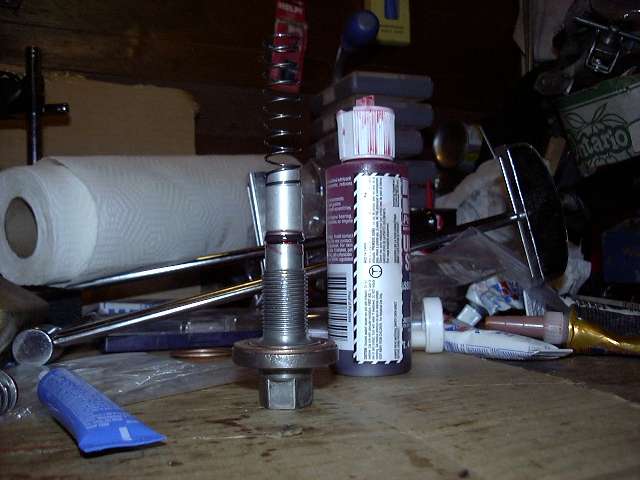
Sometimes you have to improvise. You see here a chain that is being used to hold the engine stationary while the front bolt is torqued to 90 Ft-LBS. Since there is no flywheel installed yet, a locking bar can't be used. This method works out well, but make sure that the hub is firm (a SLIGHT hit with an impact wrench helps) before you do this...You don't want the action of the chain pulling up on the hub while you are torquing.
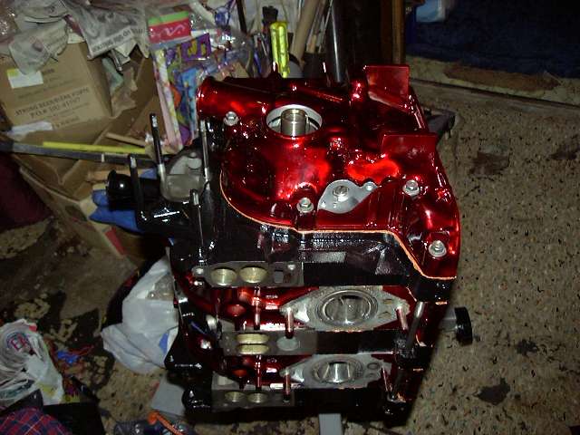
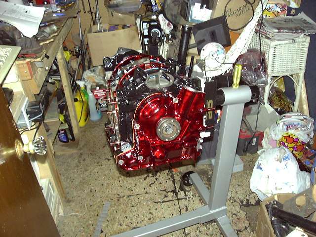
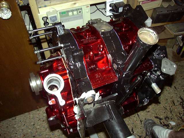
And the short block is finished. Various views. Now that the front hub is installed, the engine can be rotated. She's pretty strong already. Good solid pops. Resist the urge to spin it over too much, because you don't want to defeat the purpose of pre-lubing by wearing it off.
Anyone assembling an engine should always replace the front oil thermostat with a thermal pellet. This assures full oil flow at all times to the rotor oil jets. These pellets are available from every vendor. This one happens to be from Speed Machine, since I got a bunch the first year at Revolution.
Of course, a new o-ring should be installed and pre-lubed. Don't neglect the copper sealing washer. I super glue it in place so it doesn't come off and get crushed during assembly. Loctite should be used on this bolt. If you are going to be the next one to disassemble the engine, use blue. If it is someone else's problem, use red. Sometimes you have to improvise. You see here a chain that is being used to hold the engine stationary while the front bolt is torqued to 90 Ft-LBS. Since there is no flywheel installed yet, a locking bar can't be used. This method works out well, but make sure that the hub is firm (a SLIGHT hit with an impact wrench helps) before you do this...You don't want the action of the chain pulling up on the hub while you are torquing.
And the short block is finished. Various views. Now that the front hub is installed, the engine can be rotated. She's pretty strong already. Good solid pops. Resist the urge to spin it over too much, because you don't want to defeat the purpose of pre-lubing by wearing it off.
 08-04-04, 06:23 PM
#12
Engine, Not Motor
Thread Starter
iTrader: (1)
Join Date: Feb 2001
Location: London, Ontario, Canada
Posts: 29,789
Likes: 0
Received 108 Likes
on
91 Posts
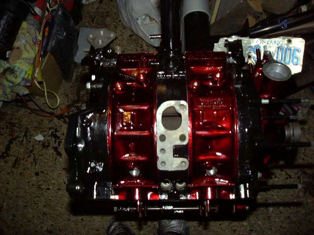
Good (sort of) shot of Mazda logo. Will be highlighted in black (or maybe silver?).
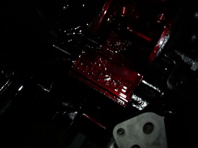
I still need to make a blockoff for the EGR ports.
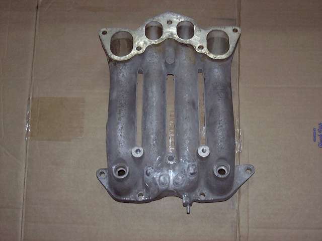
Since everyone will be asking, here's the progress on the modded lower intake. Note that I did NOT want this to turn into a major project. It was simply supposed to be a "make work" activity to do while waiting for parts. I wanted to at least feel like I was accomplishing something. Little did I know. Here is the intake with some cleanup done, and all the ports (5th and 6th, emissions) welded up. Thanks to Chris at CP Racing for having the aluminum welded up.
 08-04-04, 06:23 PM
#13
Engine, Not Motor
Thread Starter
iTrader: (1)
Join Date: Feb 2001
Location: London, Ontario, Canada
Posts: 29,789
Likes: 0
Received 108 Likes
on
91 Posts
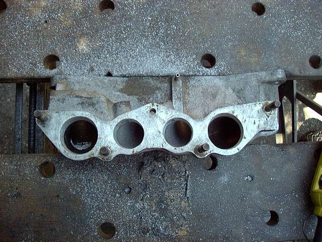
Something similar was done to the upper intake. The cold start mount was removed, and the extra vacuum nipples welded up. However, I may not use it after all...
Almost ready to be painted. The welds were smoothed down with the die grinder and sandpaper rolls. All that remains is for the carbon to be cleaned off, and for it to get a quick polish.
Before polishing, I decided that I might as well port the flanges to more closely match the gasket and engine ports.
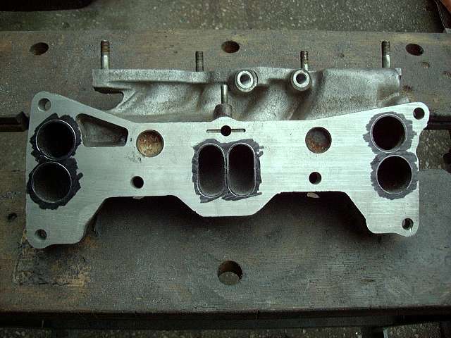
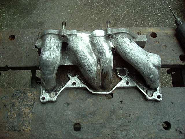
The lower flange is rough ported.
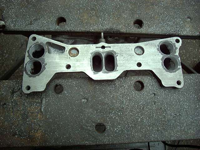
And the upper flange is rough ported. This is also the last picture. I'm going to make everyone wait for the final product in the next set of pictures that I post.
I'm hoping to post the next set of pics in a few weeks. These should include final assembly of the engine (excluding upper intake), some interior work, engine installation and related work.
It's a great feeling to see a bunch of parts finally being turned into an engine, and I'm sure it'll be a blast to see it sitting in it's nice clean engine bay. There's still a lot of work to be done though. The Microtech needs to be wired, as well as all the "extra" wiring for sound and accessories. The interior needs to be done (seats, carpet, door panels, some trim). The fuel system is a biggie as well (some decisions need to be made on that), and of course a whole new exhaust. I'll be running the stock turbo during breakin, but afterwards I'll be upgrading. Which probably means a new set of intercooler pipes and certainly a new intercooler as well.
Almost ready to be painted. The welds were smoothed down with the die grinder and sandpaper rolls. All that remains is for the carbon to be cleaned off, and for it to get a quick polish.
Before polishing, I decided that I might as well port the flanges to more closely match the gasket and engine ports.
The lower flange is rough ported.
And the upper flange is rough ported. This is also the last picture. I'm going to make everyone wait for the final product in the next set of pictures that I post.
I'm hoping to post the next set of pics in a few weeks. These should include final assembly of the engine (excluding upper intake), some interior work, engine installation and related work.
It's a great feeling to see a bunch of parts finally being turned into an engine, and I'm sure it'll be a blast to see it sitting in it's nice clean engine bay. There's still a lot of work to be done though. The Microtech needs to be wired, as well as all the "extra" wiring for sound and accessories. The interior needs to be done (seats, carpet, door panels, some trim). The fuel system is a biggie as well (some decisions need to be made on that), and of course a whole new exhaust. I'll be running the stock turbo during breakin, but afterwards I'll be upgrading. Which probably means a new set of intercooler pipes and certainly a new intercooler as well.

 08-04-04, 08:09 PM
#22
we...yota...
Join Date: Feb 2001
Location: home
Posts: 321
Likes: 0
Received 0 Likes
on
0 Posts
This might have been covered and I missed reading it but what kind of paint did you use on the housings? Is it a powdercoating? Also wondering, you're using NA housings and parts, but are you using the NA high compression rotors as well? BTW the color scheme looks absolutely wicked.
08-04-04, 09:44 PM
#24
Need an E6x

Join Date: Aug 2001
Location: Phoenix, AZ
Posts: 842
Likes: 0
Received 0 Likes
on
0 Posts
i just hope too many people don't take advantage of his pictures and do crazy things with his pics of himself!
But good writeup man. how long did it take you to assemble the engine?
and why didn't you do it in your garage? carrying it up basement steps would be a bitch i'd think.
But good writeup man. how long did it take you to assemble the engine?
and why didn't you do it in your garage? carrying it up basement steps would be a bitch i'd think.
08-04-04, 09:47 PM
#25
I'm awesome!
Join Date: Apr 2004
Location: Greenville, SC & Atlanta, GA & Clovis, NM
Posts: 1,311
Likes: 0
Received 0 Likes
on
0 Posts
Very descriptive of what was going on in the photo's. Aaron did an excellent job.
LOL, i would be weary of letting those pictures of you getting out on the internet though.
LOL, i would be weary of letting those pictures of you getting out on the internet though.